
Quick answer: The LINE terminals on a GFCI receive power from the panel. The LOAD terminals are optional outputs that can extend GFCI protection to additional receptacles or equipment downstream. A single GFCI receptacle can therefore protect more than its own face, but only when the device is listed for feed-through protection, the incoming and outgoing conductors are identified correctly, the manufacturer’s instructions are followed, and every protected outlet is tested after installation.
LINE and LOAD are not interchangeable labels for “top” and “bottom.” Terminal position and layout can vary by device. Never identify conductors by screw position, wire color alone, or the way an old receptacle was connected. A qualified person should de-energize the circuit, verify the absence of voltage, separate the conductors, identify the supply cable with appropriate test equipment, and then follow the markings on the exact GFCI.
This guide explains the operating logic and the checks a buyer, contractor, or maintenance team should require. It is not a substitute for the product instructions, the locally adopted electrical code, or work by a qualified electrician.
GFCI LINE vs. LOAD at a Glance
| Item | LINE terminals | LOAD terminals |
|---|---|---|
| Main function | Accept the incoming branch-circuit supply | Send power through the GFCI to selected downstream outlets |
| Required for the device face to work | Yes | No |
| Provides feed-through protection | Not applicable | Yes, when correctly used on a listed device |
| Typical conductors | Incoming ungrounded and grounded conductors | Outgoing ungrounded and grounded conductors serving downstream loads |
| Common error | Supply landed on LOAD or mixed with outgoing conductors | Unprotected conductors mistaken for protected outputs |
| Verification | Device powers, resets, and trips as instructed | Every intended downstream outlet loses power when the controlling GFCI trips |
The equipment grounding conductor is not a LINE or LOAD current-carrying conductor. It is connected to the grounding terminal and enclosure as required. Neutral conductors also must stay paired with the correct hot conductors. Borrowed neutrals, multiwire branch circuits, shared-neutral arrangements, and crowded boxes require additional design judgment; they should not be “solved” by trial and error at a receptacle.
What the LINE Terminals Do
The LINE terminals are the input to the protection device. They connect the GFCI electronics and sensing mechanism to the branch-circuit supply. Without a correct LINE connection, the device cannot perform as designed.
Modern GFCI receptacles commonly include miswire protection or reset lockout. Depending on the model, a reverse LINE/LOAD connection may prevent reset, deny power to the face, or produce another indication. That safety behavior is useful, but it is not a wiring method. An installer still has to identify the supply conductors and comply with the exact instruction sheet.
Leviton’s official GFCI LINE/LOAD reversal support page illustrates why model-specific behavior matters. Its instructions should not be generalized to every brand or generation. The label molded or printed on the device and the instruction sheet supplied with that catalog number control the connection.
What the LOAD Terminals Do
The LOAD terminals allow the GFCI to monitor current flowing to downstream outlets. If an imbalance reaches the device’s trip threshold, the GFCI opens the circuit and removes power from its face and the protected LOAD output.
This is called feed-through or downstream protection. It can be useful when several receptacles in a bathroom, garage, unfinished basement, utility area, or kitchen need protection and the controlling GFCI remains accessible for testing and resetting.
LOAD is optional. If no downstream protection is intended, the factory warning tape or cover over the LOAD terminals should remain in place until the installer has confirmed that those terminals are needed. Attaching extra conductors merely because terminals are available can create an undocumented protection chain that is difficult to service.
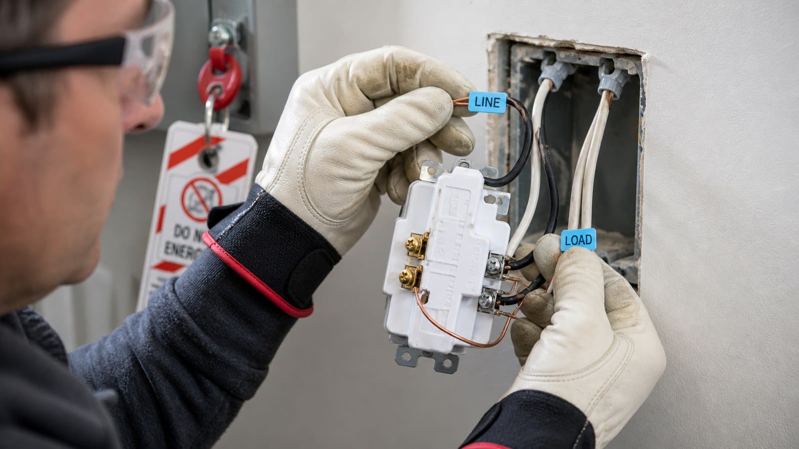
Editorial application scene: a de-energized wall box with incoming and downstream cables being identified before connection.
Why Terminal Position Is an Unsafe Shortcut
Internet diagrams often say LINE is always on the bottom or always on the top. That shortcut is unreliable. Devices differ by manufacturer, product family, form factor, and generation. A receptacle can also be installed with the grounding contact oriented up or down, which makes positional advice even less useful.
Use three sources of truth:
- The LINE and LOAD markings on the exact device.
- The wiring diagram and instructions supplied with that catalog number.
- Electrical measurements made under a safe, controlled procedure by a qualified person.
Wire color is not sufficient proof. White is normally used for grounded conductors and black or red for ungrounded conductors, but alterations, re-identification, switch loops, shared neutrals, and past mistakes can defeat visual assumptions. The cable that seems to “come from the panel direction” is not proof either.
How a Qualified Person Identifies LINE and LOAD
The following is a planning-level sequence, not a live-work tutorial.
- Turn off the correct branch circuit. Apply the site’s lockout or control procedure where required.
- Verify the tester. Confirm the voltage tester on a known source before and after the absence-of-voltage check.
- Verify de-energization. Check all relevant conductors and grounding paths. Do not rely only on a non-contact tester.
- Separate and identify cables. Keep conductor pairs organized so the neutral belonging to each cable is not mixed.
- Energize only for controlled identification if the work procedure permits it. A qualified person can determine which cable is the supply. Everyone else should stop and call an electrician.
- De-energize and reverify. Connect the identified supply to LINE and any intentionally protected outgoing cable to LOAD according to the instructions.
- Complete grounding, torque, box-fill, and terminal checks. Use the listed connection method and specified conductor range. Do not put two conductors under a terminal unless the device is identified for it.
- Test before closing the job. Confirm the GFCI face and each downstream outlet operate and trip correctly.
The official Leviton GFCI receptacle instruction sheet shows the kind of device-specific identification and testing information that belongs at the work location.
How Downstream Protection Works in Real Rooms
Consider a bathroom with a GFCI receptacle at the vanity and an ordinary tamper-resistant receptacle on another wall. If the second receptacle is connected to the GFCI’s LOAD output, pressing TEST on the controlling GFCI should remove power at both locations. Resetting the GFCI should restore power, assuming no fault remains.
The downstream receptacle does not need TEST and RESET buttons merely because it is GFCI protected. It does need to be clearly identified where the applicable code or product instructions require marking. Labels such as “GFCI Protected” and “No Equipment Ground” have specific uses; do not apply the second label unless the grounding condition actually calls for it.
In a garage, one accessible GFCI may protect several wall receptacles. That reduces device count, but it also creates a service dependency: a trip at the first device can shut off a freezer, charger, door operator, or workbench receptacle farther away. The layout should make the controlling device easy to find and should consider the consequences of losing multiple loads together.
For room-specific planning, Faith’s bathroom GFCI requirements guide explains how protection, receptacle placement, and the required 20A circuit interact.
GFCI at Every Outlet or One GFCI Upstream?
Both approaches can be valid when correctly designed. The better choice depends on access, service impact, labeling, project standards, and total installed cost.
| Design choice | Advantages | Tradeoffs |
|---|---|---|
| GFCI receptacle at each location | Local TEST/RESET access; easier to identify which load tripped; one trip usually affects fewer outlets | More GFCI devices to purchase and maintain; deeper devices may challenge crowded boxes |
| One GFCI with LOAD-side protection | Fewer protection devices; can protect several downstream receptacles from one accessible point | One trip can remove power from many outlets; reset point may be hard to find; downstream mapping and labels are essential |
| GFCI circuit breaker | Protects the circuit from the panel; useful where a receptacle device is impractical | Reset requires panel access; compatibility and neutral routing matter; may interrupt every outlet on the circuit |
Do not choose only by device price. A lower material count can create higher service cost when occupants cannot find the reset point. In multifamily, hospitality, retail, and property-management projects, a simple protection map can be more valuable than saving one receptacle.
Finished-Installation Test for Feed-Through Protection
Testing should prove the protection boundary, not merely make the button click.
- Plug an appropriate receptacle tester or test load into the GFCI face and each intended downstream receptacle.
- Press the GFCI TEST button. The device should trip and power should be removed as described in its instructions.
- Check every downstream outlet on the circuit map. Each outlet intended to be protected by that GFCI should be de-energized.
- Check outlets that are not intended to be controlled. Unexpected loss of power may reveal an undocumented LOAD connection.
- Press RESET and confirm normal power returns.
- Record the controlling device, downstream locations, test date, and any label applied.

Editorial application scene: testing an accessible GFCI and confirming that an intended downstream receptacle loses power.
OSHA explains that GFCIs should be tested according to the manufacturer’s instructions and notes that a tester does not replace required inspection and maintenance. See OSHA’s official GFCI testing interpretation. Workplace programs may impose additional requirements beyond a residential project.
Common LINE/LOAD Problems and What They Look Like
The New GFCI Will Not Reset
Possible causes include reversed LINE/LOAD, no incoming power, an open neutral, a fault on the LOAD side, a mispaired neutral, or a failed device. Do not repeatedly force RESET. Remove downstream conductors only as part of a qualified diagnostic procedure, then test the device and circuit against the instructions. Faith’s GFCI won’t reset guide covers the broader symptom safely.
The GFCI Face Trips but Another Outlet Stays Live
The other outlet may not be on the GFCI LOAD output, may be supplied by a different circuit, or may be connected ahead of the protection device. Trace and document the circuit rather than assuming that physical proximity means electrical connection.
Several Rooms Lose Power Together
This can be the expected result of an upstream GFCI protecting a long downstream chain. It may also indicate that the protection boundary is broader than the project intended. Find the controlling GFCI, identify every affected outlet, and decide whether local protection would produce a more serviceable design.
A Downstream GFCI Is Connected to Another GFCI
Series GFCI devices are not automatically prohibited, but they can make trip location confusing and are often unnecessary. If two devices protect the same load, either may trip depending on the fault and device tolerances. The project should have a documented reason for the arrangement and clear reset access.
Buyer and Project Specification Checklist
For OEM, private-label, distribution, or project procurement, require enough information to evaluate the complete device rather than just the face style.
- Listing and certification appropriate to the U.S. market and the exact catalog number.
- Self-test or auto-monitoring behavior and reset-lockout description.
- Clear LINE and LOAD markings that remain readable during installation.
- Factory protection over LOAD terminals and a model-specific wiring diagram.
- Feed-through current rating, voltage, frequency, conductor range, terminal method, and torque instructions.
- 15A or 20A receptacle configuration selected for the branch-circuit design.
- Tamper-resistant, weather-resistant, hospital-grade, or other construction only where the application requires it.
- Status-indicator logic stated in the instruction sheet; do not rely on universal LED-color assumptions.
- English packaging, installation instructions, warning labels, date/lot traceability, and replacement policy.
- Samples evaluated for terminal access, box fit, labeling clarity, TEST/RESET feel, and downstream trip behavior.
For private-label programs, Faith Electric has manufactured wiring devices since 1996. Buyers should still verify the exact listing path, model scope, markings, packaging, and approval documents for their program. See the private-label GFCI OEM checklist for a broader sourcing workflow.
Frequently Asked Questions
Can I connect two wires to the GFCI LINE terminals?
Only if the exact device is identified and listed for that conductor arrangement and size. Otherwise use a listed splice and pigtail method that complies with box-fill and installation rules. Do not place multiple conductors under a screw simply because they physically fit.
Does the LOAD side have power when the GFCI is tripped?
A correctly operating GFCI should remove power from its protected LOAD output when it trips. Verify the exact device instructions and test every intended downstream outlet; do not infer protection from wiring appearance.
Can a regular outlet be GFCI protected?
Yes. An ordinary receptacle can be protected by an upstream GFCI receptacle or GFCI circuit breaker. It should be tested at the finished installation and labeled where required.
Is LINE always the bottom pair of screws?
No. Position varies. Read the LINE and LOAD markings on the exact device and its instructions.
Can I use the LOAD terminals as extra splice points?
Not unless the outgoing circuit is intentionally meant to receive feed-through GFCI protection and the connection complies with the device listing. LOAD terminals change the protection boundary; they are not generic spare terminals.
Why does the GFCI trip when I connect the LOAD wires?
The downstream wiring or equipment may have a ground fault, neutral-to-ground connection, crossed or shared neutral, moisture problem, or other defect. De-energize the circuit and have a qualified electrician isolate the cause. Do not bypass the GFCI to keep the load running.
Bottom Line
LINE brings power into a GFCI. LOAD sends monitored power to selected downstream outlets. That simple distinction has important consequences for safety, serviceability, labeling, and procurement.
The reliable workflow is to identify conductors with the circuit de-energized, follow the exact device markings and instructions, connect LOAD only when downstream protection is intentional, and test every outlet in the protection map. Buyers should specify feed-through performance, markings, instructions, traceability, and the features needed for the application—not just amperage and color.
Safety disclaimer: This article provides general U.S. planning and procurement information. Electrical work can cause shock, arc-flash, fire, or equipment damage. Follow the locally adopted code, the authority having jurisdiction, site safety procedures, and the instructions for the exact product. Use a licensed or otherwise qualified electrician for installation and diagnosis.